Customized support: yes
Model Number: FR500A-4T-4.0G/5.5PB
Type: AC to AC
Output Type: Triple
Output Current: 9.5 A
Output Frequency: 0.00~ 600.00Hz; unit: 0.01Hz
Size: 117*187*175mm
Weight: 2kg
Certificate: CE
Certificates: CE, ISO9001:2008 for ac drive
Input terminals: DI-7(HDI-1), AI-3 0~10V, or 0-20mA
Output terminals: DO-2(HDO-1), RO-2, AO-2
Applicable motors: Asynchronous motor and synchronous motor
Speed control accuracy: ±0.5% (SVC1); ±0.2%;(SVC2);
Overload capacity: 1 minute for 150% ; 10s for 180%; 1s for 200%
Starting torque: 0.5HZ:180% (SVC1); 0.25HZ:180%;(SVC2); 0HZ:200%( Vector control);
Adjusting speed range: 1:100 (V/F control); 1:200 (SVC1, SVC2);
Control techniques: V/F, SVC1, SVC2
IGBT and DSP: Infineon and Spansion for micro grid tie inverter
Packaging Details: Carton boxes for small power VFDs, wodden boxes for 55KW or above VFDs
| Project | Specifications | ||||
| Power input | Rated input voltage (V) | 3-phase 380 V (-15%~+30%) | |||
| Rated input current (A) | See table 2-1 | ||||
| Rated input frequency(Hz) | 50Hz/60Hz,tolerance±5% | ||||
| Power output | Applicable motor(kW) | See table 2-1 | |||
| Rated output current(A) | See table 2-1 | ||||
| The maximum output voltage(V) | 0~rated input voltage, error< JD Braided Adjustable Black Leather Rope Wax Cord Lobster Clasp String Cord Jewelry Chains for DIY Handmade Necklace Pendant ±3% | ||||
| The maximum output frequency(Hz) | 0.00~600.00 Hz,unit0.01Hz | ||||
| Controlcharacteristics | V/f patterns | V/f controlSensor-less vector control 1Sensor-less vector control 2 | |||
| Speed range | 1:50 (V/f control)1:100 (sensor-less vector control 1)1:200(sensor-less vector control 2) | ||||
| Speed accuracy | ±0.5% (V/f control)±0.2% (sensor-less vector control 1 & 2) | ||||
| Speed fluctuation | ±0.3% (sensor-less vector control 1 & 2) | ||||
| Torque response | < 10ms (sensor-less vector control 1 & 2) | ||||
| Starting torque | 0.5Hz: 180% (V/f control, sensor-less vector control 1)0.25Hz: 180% (sensor-less vector control 2) | ||||
| Basic functions | Carrier frequency | 0.7kHz~16kHz | |||
| Overload capability | G Model:150% Rated Current 60s,180% Rated Current 10s,200% Rated Current 1s.P Model:120% Rated Current 60s,145% Rated Current 10s,160% Rated Current 1s. | ||||
| Torque boost | Automatic torque boost;Manual torque boost 0.1%~30.0% | ||||
| V/F Curve | Three ways:Three ways: straight; multi-point type; N Th-type V / F curve(1.2 Th -type, 1.4 Th -type, 1.6 Th -type, 1.8 Th -type, 2Th -type) | ||||
| Acceleration and deceleration Curve | Line or curve acceleration and deceleration mode.Four kinds of acceleration and deceleration time,Ramp Time Range :0.0~6000.0s | ||||
| DC brake | DC brake start frequency: 0.00~600.00HzDC brake time:0.0s~10.0sDC brake current:0.0%~150.0% | ||||
| Basic functions | Jog brake | Jog frequency range:0.00Hz~50.00Hz.Jog deceleration time: 0.0s~6000.0s. | |||
| Simple PLC, Multi-speed | Through the built-in PLC or control terminal to achieve up to 16 speed running | ||||
| Built-in PID | Facilitate the realization of process control loop control system | ||||
| Automatic voltage adjustment(AVR) | When the grid voltage changes, can automatically maintain a constant output voltage | ||||
| Fast current limit function | Minimize over current fault protection inverter running | ||||
| Over voltage Over current | System automatically limits of current and voltage during operation to prevent frequent | ||||
| Run | Command source | Given the control panel, Wholesale New Products Adjustable Gas Ballast Valve Rotary Vane Vacuum Pump Centrifugal Pump Price control terminal, serial communication port given. | |||
| Frequency given | 9 kinds of frequency given sources: digital setting, keyboard potentiometer setting, analogVoltage, given analog current reference pulse is given, the serial port is given, multi-speed given, PLC is given, the process PID reference. There are several ways to switch | ||||
| Input terminal | 7 Switch input terminals, 1 way to make high-speed pulse input.3-channel analog inputs, including 2-way 0~10V / 0~20mA voltage and current options,a way to support -10~+10 V input | ||||
| outputterminal | 2-way switch output terminal, which supports a maximum road speed 100kHz pulse output.2 relay output terminals.2 analog output terminal, and optional voltage and current. | ||||
| Featuredfunctions | Parameter copy, parameter backup, flexible parameter displayed & hidden. Common DC bus(Contains below 30 KW).Various master & auxiliary command and switchover.Reliable speed search started.A variety of Accel / Decel curves programmable.Timing control, fixed length control, count function.Three faults recorded.Over excitation brake, overvoltage stall protection programmable, under voltage stall protection programmable, restart CZPT powerloss.Four kinds of Accel/Decel time.Motor thermal protection.Flexible fan control.Process PID control, simple PLC, 16-step speed control programmable.Wobble frequency control.Multi-functional key programmable, LW10008 8bar 115psi 1m3min 30CFM piston air compressor 7.5kw 10hp field-weakening control.High-precision torque control, V/f separated control, torque control at sensor-less vector control. | ||||
| Protectionfunction | Provide fault protection dozen: Overcurrent, Overvoltage, Undervoltage, Overtemperature, Overload Etc Protection. | ||||
| Display and keyboard | LED Display | Display Parameters | |||
| Key lock and function selection | Realize some or all of the keys locked, scope definition section keys to prevent misuse | ||||
| Run and stop monitoring information | In the run or stop can be set to monitor U00 group 4 objects were. | ||||
| Environment | Place ofoperation | Indoors, no direct sunlight, free from dust, corrosive gases,flammable gases, oil mist, water vapor, water drop and salt, etc. | |||
| Altitude | 0~2000mDe-rate 1% for every 100m when the altitude is above 1000 meters | ||||
| Ambienttemperature | -10℃~40℃ | ||||
| Relativehumidity | 5~95%, no condensation | ||||
| Vibration | Less than 5.9m/s2 (0.6g) | ||||
| Storagetemperature | -20℃~+70℃ | ||||
| Others | Efficiency | Rated power≥93% | |||
| Installation | Wall-mounted or Flange mounting | ||||
| IP grade | IP20 | ||||
| Coolingmethod | Fan cooled | ||||

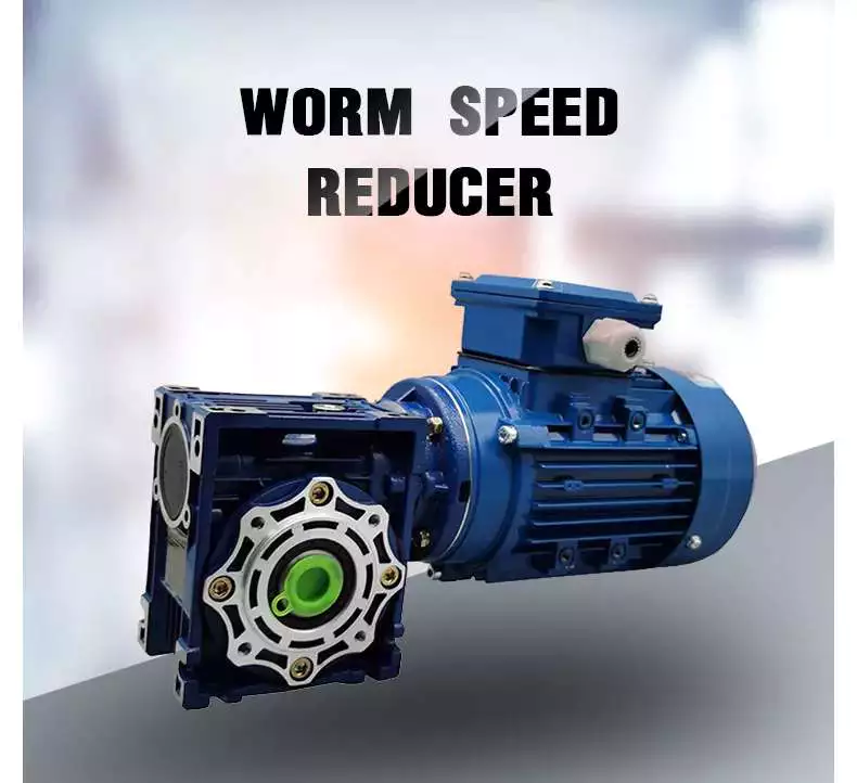
What is a worm gear reducer?
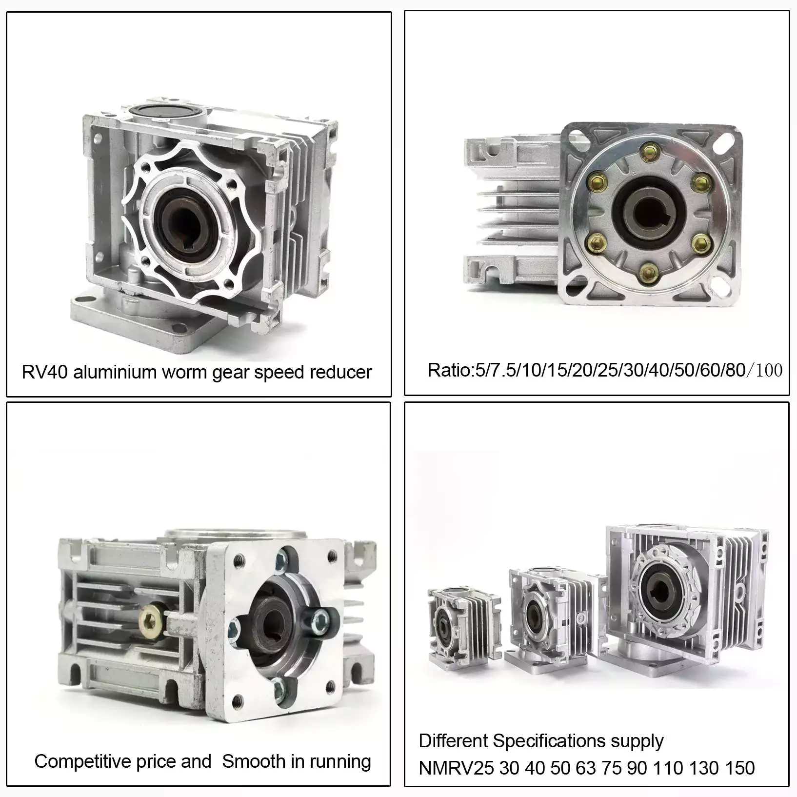
A worm gear reducer is a mechanical device that uses a worm gear and a worm to reduce the speed of a rotating shaft. The gear reducer can increase the output torque of the engine according to the gear ratio. This type of gear reducer is characterized by its flexibility and compact size. It also increases the strength and efficiency of the drive.
Hollow shaft worm gear reducer
The hollow shaft worm gear reducer is an additional output shaft connecting various motors and other gearboxes. They can be installed horizontally or vertically. Depending on size and scale, they can be used with gearboxes from 4GN to 5GX.
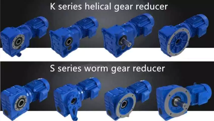
Worm gear reducers are usually used in combination with helical gear reducers. The latter is mounted on the input side of the worm gear reducer and is a great way to reduce the speed of high output motors. The gear reducer has high efficiency, low speed operation, low noise, low vibration and low energy consumption.
Worm gear reducers are made of hard steel or non-ferrous metals, increasing their efficiency. However, gears are not indestructible, and failure to keep running can cause the gear oil to rust or emulsify. This is due to moisture condensation that occurs during the operation and shutdown of the reducer. The assembly process and quality of the bearing are important factors to prevent condensation.
Hollow shaft worm gear reducers can be used in a variety of applications. They are commonly used in machine tools, variable speed drives and automotive applications. However, they are not suitable for continuous operation. If you plan to use a hollow shaft worm gear reducer, be sure to choose the correct one according to your requirements.
Double throat worm gear
Worm gear reducers use a worm gear as the input gear. An electric motor or sprocket drives the worm, which is supported by anti-friction roller bearings. Worm gears are prone to wear due to the high friction in the gear teeth. This leads to corrosion of the confinement surfaces of the gears.
The pitch diameter and working depth of the worm gear are important. The pitch circle diameter is the diameter of the imaginary circle in which the worm and the gear mesh. Working depth is the maximum amount of worm thread that extends into the backlash. Throat diameter is the diameter of the circle at the lowest point of the worm gear face.
When the friction angle between the worm and the gear exceeds the lead angle of the worm, the worm gear is self-locking. This feature is useful for lifting equipment, but may be detrimental to systems that require reverse sensitivity. In these systems, the self-locking ability of the gears is a key limitation.
The double throat worm gear provides the tightest connection between the worm and the gear. The worm gear must be installed correctly to ensure maximum efficiency. One way to install the worm gear assembly is through a keyway. The keyway prevents the shaft from rotating, which is critical for transmitting torque. Then attach the gear to the hub using the set screw.
The axial and circumferential pitch of the worm gear should match the pitch diameter of the larger gear. Single-throat worm gears are single-threaded, and double-throat worm gears are double-throat. A single thread design advances one tooth, while a double thread design advances two teeth. The number of threads should match the number of mating gears.
Self-locking function
One of the most prominent features of a worm reducer is its self-locking function, which prevents the input and output shafts from being interchanged. The self-locking function is ideal for industrial applications where large gear reduction ratios are required without enlarging the gear box.
The self-locking function of a worm reducer can be achieved by choosing the right type of worm gear. However, it should be noted that this feature is not available in all types of worm gear reducers. Worm gears are self-locking only when a specific speed ratio is reached. When the speed ratio is too small, the self-locking function will not work effectively.
Self-locking status of a worm reducer is determined by the lead, pressure, and coefficient of friction. In the early twentieth century, cars had a tendency to pull the steering toward the side with a flat tire. A worm drive reduced this tendency by reducing frictional forces and transmitting steering force to the wheel, which aids in steering and reduces wear and tear.
A self-locking worm reducer is a simple-machine with low mechanical efficiency. It is self-locking when the work at one end is greater than the work at the other. If the mechanical efficiency of a worm reducer is less than 50%, the friction will result in losses. In addition, the self-locking function is not applicable when the drive is reversed. This characteristic makes self-locking worm gears ideal for hoisting and lowering applications.
Another feature of a worm reducer is its ability to reduce axially. Worm gears can be double-lead or single-lead, and it is possible to adjust their backlash to compensate for tooth wear.
Heat generated by worm gears
Worm gears generate considerable amounts of heat. It is essential to reduce this heat to improve the performance of the gears. This heat can be mitigated by designing the worms with smoother surfaces. In general, the speed at which worm gears mesh should be in the range of 20 to 24 rms.
There are many approaches for calculating worm gear efficiency. However, no other approach uses an automatic approach to building the thermal network. The other methods either abstractly investigate the gearbox as an isothermal system or build the TNM statically. This paper describes a new method for automatically calculating heat balance and efficiency for worm gears.
Heat generated by worm gears is a significant source of power loss. Worm gears are typically characterized by high sliding speeds in their tooth contacts, which causes high frictional heat and increased thermal stresses. As a result, accurate calculations are necessary to ensure optimal operation. In order to determine the efficiency of a gearbox system, manufacturers often use the simulation program WTplus to calculate heat loss and efficiency. The heat balance calculation is achieved by adding the no-load and load-dependent power losses of the gearbox.
Worm gears require a special type of lubricant. A synthetic oil that is non-magnetic and has a low friction coefficient is used. However, the oil is only one of the options for lubricating worm gears. In order to extend the life of worm gears, you should also consider adding a natural additive to the lubricant.
Worm gears can have a very high reduction ratio. They can achieve massive reductions with little effort, compared to conventional gearsets which require multiple reductions. Worm gears also have fewer moving parts and places for failure than conventional gears. One disadvantage of worm gears is that they are not reversible, which limits their efficiency.
Size of worm gear reducer
Worm gear reducers can be used to decrease the speed of a rotating shaft. They are usually designed with two shafts at right angles. The worm wheel acts as both the pinion and rack. The central cross section forms the boundary between the advancing and receding sides of the worm gear.
The output gear of a worm gear reducer has a small diameter compared to the input gear. This allows for low-speed operation while producing a high-torque output. This makes worm gear reducers great for space-saving applications. They also have low initial costs.
Worm gear reducers are one of the most popular types of speed reducers. They can be small and powerful and are often used in power transmission systems. These units can be used in elevators, conveyor belts, security gates, and medical equipment. Worm gearing is often found in small and large sized machines.
Worm gears can also be adjusted. A dual-lead worm gear has a different lead on the left and right tooth surfaces. This allows for axial movement of the worm and can also be adjusted to reduce backlash. A backlash adjustment may be necessary as the worm wears down. In some cases, this backlash can be adjusted by adjusting the center distance between the worm gear.
The size of worm gear reducer depends on its function. For example, if the worm gear is used to reduce the speed of an automobile, it should be a model that can be installed in a small car.


editor by Cx 2023-07-13