Model Number: MD300-C0015G3
Warranty: 18months
Type: AC-DC-AC
Certification: CE ISO9001
Customized: NO
Rated Power: 1.5KW
Nominal Voltage: 380V
power phase number: 3 phase
Overload: 150%- 60s,180%- 3s
Color: Black
Output Frequency: 0-500hz
Protection: IP20
Output waveform: PWM
Control model: V/F,SVC
Application: 3 Phase AC Asynchronism Motor
Shipment: Sea/air
Market: Worldwide
Other service: OEM
Packaging Details: All the product are packaged with single small carton or plywood crate.
3 Phase 380v Variable Frequency Drive 1.5kw Speed Variator
| Model | MD300-C0015G3 |
| Power range | AC 380V (-15%~+30%) 1.5kw |
| Output Frequency Range | 0~500Hz |
| Control Mode | V/F Control, Sensorless Vector Control |
| Starting Torque | 0.5Hz/150%(SVC), 1Hz/150%(V/F); |
| Communication port | RS-485, which support MODBUS protocol,this is option |
| Vibration | Less than 5.9m/s |
| Fault Protection | protect from over current, over voltage, under voltage, over temperature, phase failure, over load etc. |
MD300 series frequency inverter detail size and current
| Voltage | Power | Current | Dimension mm H *W * D | Installation size mm H1* W1 | Hole | |||
| 220v | 0.75kw | 4A | 170 | 86 | 131.5 | 159 | 75 | 5mm |
| 220v | 1.5kw | 7A | 170 | 86 | 131.5 | 159 | 75 | 5mm |
| 380v | 0.75kw | 2.5A | 170 | 86 | 131.5 | 159 | 75 | 5mm |
| 380v | 1.5kw | 3.7A | 170 | 86 | 131.5 | 159 | 75 | 5mm |
| 380v | 2.2kw | 5.1A | 170 | 86 | 131.5 | 159 | 75 | 5mm |
Specification
| Item | Specifications | |
| Basic function | Over load capability | G type:150% rated current 60s;180% rated current 3s |
| P type:120% rated current 60s;150% rated current 3s | ||
| Torque boost | Auto torque boost function; Manual torque boost 0.1%~30.0% | |
| V/F curve | Linear V/F, multi-point V/F and square V/F curve(power of 1.2,1.4,1.6,1.8,2) | |
| V/F separation | 2 ways: separation and semi-separation | |
| Acc./dec curve | Straight line or S curve acceleration and deceleration mode, | |
| Four kinds of acceleration and deceleration time. Acceleration and deceleration time range from 0.0s to 6500.0s | ||
| DC braking | DC braking frequency:0.00Hz to maximum frequency. Braking time:0.0s to 36.0s | |
| Brake current value:0%-100% | ||
| Jog control | Jog frequency range:0.00Hz~50.00Hz; | |
| Jog acceleration/deceleration:0.0s~6500.0s. | ||
| Simple PLC | It can realize at maximum of 16 segments speed | |
| Basic function | Multiple segment speed running | Running via the built-in PLC or control terminal. |
| Built-in PID | It is easy to realize process-controlled closed loop control system. | |
| Auto voltage regulation (AVR) | It can keep constant output voltage automatically in the case of change of network voltage. | |
| Over-voltage/current stall control | It can limit the running voltage/current automatically and prevent frequent over-voltage/current tripping during the running process. | |
| Quick current limit | Minimize the over-current fault, protect normal operation of the AC Drive. | |
| Torque limit & control | “Excavators” characteristics, automatically limit torque during operation, prevent frequent over-current tripping. Closed loop vector mode can realize the torque control. | |
| Personalized function | Instantaneous stop non-stop | When instantaneous power off, voltage reduction is compensated through load feedback energy, which could make AC Drive keep running in a short period of time. |
| Rapid current limit | To avoid AC Drive frequent over-current fault. | |
| Timing control | Timing control function:set time range 0Min~6500.0Min. | |
| Running | Command source | Operation panel reference, control terminal reference and serial communication port reference. These channels can be switched in various modes. |
| Frequency source | There are totally 11 types of frequency sources, such as digital reference, analog voltage reference , analog current reference, pulse reference, MS speed, PLC, PID and serial port reference. | |
| Input terminal | 4 digital input terminals. | |
| 2 analog input terminals. | ||
| 1 supporting 0-10V voltage input or 0~20mA current input terminal. | ||
| Output terminal | ||
| 2 relay output terminals. | ||
| 2 analog output terminals, supporting 0~10V voltage output or 0~20mA current output. | ||
| Keyboard operation | Keyboard potentiometer | Equipped with keyboard potentiometer or coding potentiometer. |
| Keyboard operation | Protection function | It can implement power-on motor short-circuit detection, input /output phase loss protection, over current protection, over voltage protection, under voltage protection, overheating protection and overload protection. |
| Environment | Using place | Indoor, and be free from direct sunlight, dust, corrosive gas, combustible gas, oil smoke, vapor, drip or salt. |
| Altitude | Below 1000m | |
| Ambient temperature | -10 ℃ to +40 ℃ (Derating use when under ambient temperature of 40 ℃ to 50 ℃) | |
| Humidity | Less than 95%RH,without condensing | |
| Vibration | Less than 5.9m/s (0.6g) | |
Packaging & Shipping
Application
Company Information
FAQQ 1: Are you trading company or manufacturer ?A: We are factory.
Q 2: How long is your lead time?A: Generally it is 3-7 days if the goods are in stock. or it is 10-20 days if the goods are not in stock, it is according to quantity.
Q 3: Do you provide samples ? is it free or extra ?A: Yes, we could offer the sample,but we will charge the sample fee and the cost of freight.
Q 4: What is your terms of payment ?A:We accept T/T, L/C and CASH.
Q 5: What is the standard of package?
A. Export standard package or special package according to customer requirement.
Q 6. Is there any discount ?
A. The discount will depend on the quanlity you purchase.
Q 7. What is your supply capacity?
A. The daily output of the factory exceeds 2000 PCS.
Q 8.Do you provide warranty for the goods?
A. Yes, we provide 18 months of warranty for all the goods from us.
Q 9.Could M-driver provide technical support?
A.We’ have more than 15years experience in this field. If there’s any problem, please feel free to contact us, we’ll provide suggestion from our engineer to help you solve the problem.
CZPT Mechanical Speed Variator Dissectible
CZPT Mechanical Speed Variator Dissectible is part of a series of dissectable industrial gear reducers. Its heavy gauge baseplate allows students to perform realistic disassembly and inspection of a mechanical speed variator commonly encountered in industrial settings. A complete disassembly guide is also provided for the mechanical speed variator dissection training experience.
Intensity limiter
The Intensity Limiter for Speed Variator is a device that regulates the power to the motor by limiting the intensity of the starting current. This device employs a substantial portion of the variator elements and is low-cost and space-efficient. It also works at low current and power levels.
Capacitor C
The Speed Variator is composed of two main components, a rectifier module and a capacitor. The rectifier module provides the DC voltage bus and is located upstream of the inverter module. The ballast capacitor 29 is situated between the two. Both the components work together to regulate the output voltage.
The voltage across the capacitor is applied through the potentiometer P. When the current is greater than the voltage across the resistor R 4, it results in a positive half-cycle. At this point, the current from point A polarizes the Zener diode Z, which has a conduction threshold of 100 volts. In the meantime, the capacitor C continues to be charged through the potentiometer P at a constant current. Moreover, the resistance R 4 is adapted to determine the charging current required to maintain the minimum motor speed.
Another type of Speed Variator is an overspeed protection device. This device protects the motor from an overload by limiting the motor current. This component also limits the output voltage when the motor is started. This design requires low currents and low powers and reduces the overall cost of the device. In addition, it also ensures that the motor operates at low speeds. This means that the voltage at the output of the Variator should be lower than the voltage at the motor.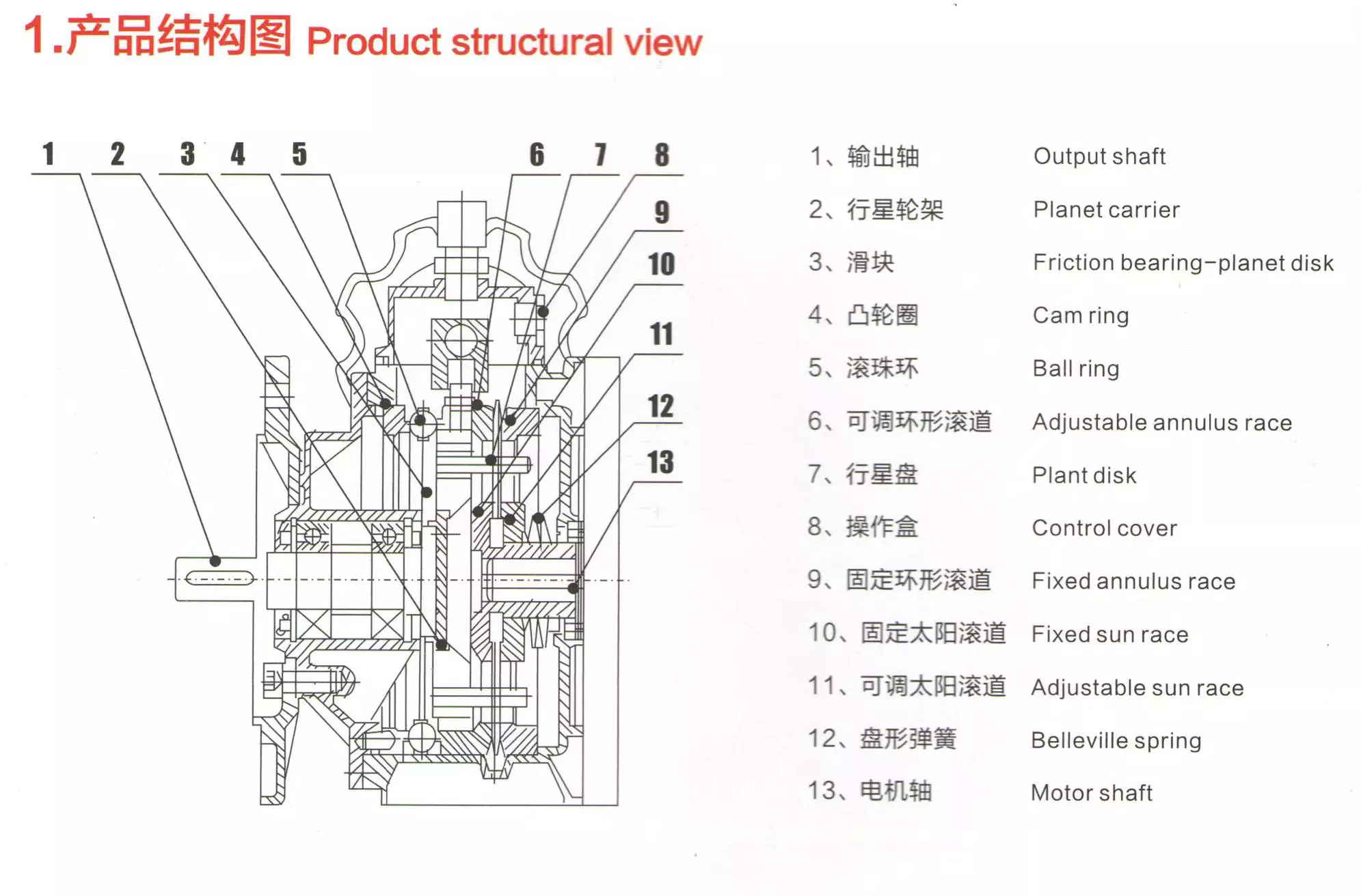
Protection circuit CP
The Speed Variator is a device that controls motor speed by adjusting a potentiometer. During normal operation, the motor can run at one half of the supply voltage or both half-cycles at high speeds. The speed regulation is automatic and the transition between these modes is seamless. In the present invention, the motor is protected from overloads by incorporating a circuit CP, which serves as a second shunt circuit for charging the capacitor C. The circuit CP requires a -ve voltage that represents the current in the motor during negative half-cycles.
The Speed Variator protection circuit CP includes two transistors with opposite polarity and common emitter configurations. The transistors are connected through their common collector resistors R 15 and R o. The transistors are protected by the circuit through diode D 3. Diode D 3 is connected in series with resistor R 16 and is connected to the junction point of the capacitor C and the resistor R o. The common collector resistor R 16 regulates the +ve voltage of the measuring circuit CM.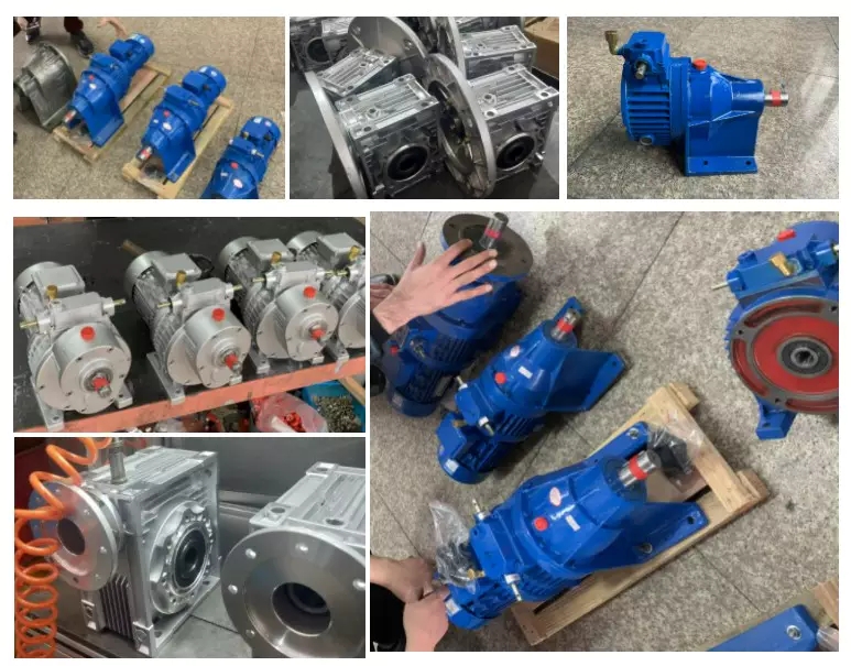
Mechanical continuous gear variator 100
A mechanical continuous gear variator 100 is a type of transmission that has multiple gears. This type of transmission includes a first shift element B1, a second shift element K1, and a third shift element C2. The first shift element B1 has a clutch or brake, while the second shift element is either a gear or a sprocket.
Mechanical continuous gear variators can be used to change the speed of an engine. This type of gearbox can be attached to a milling machine or a drill. A mechanical continuous gear variator 100 can be attached to the drive shaft of one device, while a second device can be connected to the driven shaft of another device. By adjusting the speed of the second device, the mechanical continuous gear variator 100 can make it faster or slower, and reduce or increase the amount of work needed to finish the task.
Mechanical continuous gear variator 100 comprises two groups of multiplier gears 50, 60. The drive shaft 1 is rotatably mounted on a frame 13, and the driven shaft 9 is rotatably mounted on carriage or rails. The movable translation means are coupled to adjustment means, which adjust the position of the movable translation means.
Mechanical continuous gear variator 100 functions as a variable multiplier, wherein the first group of gears performs the first multiplication and the second group performs the second. These groups then multiply the same amount, giving double the final multiplication. The ratio between the drive shaft 1 and the driven shaft 9 is 1:1. The final ratio is greatest when the carriage 10 is at its maximum translation distance.
Mechanical continuous gear variator 100 implements three shift modes. The first range, V1, is the first range. The second range, V2, is the second range. The third range is the third range. These three modes are implemented by selectively controlling the shift elements of transmission device 100. The shift elements open and close alternately at the speed-synchronized point.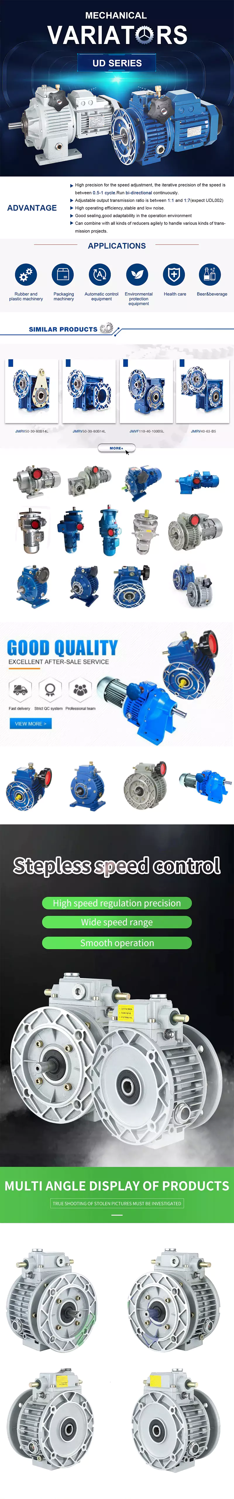
editor by czh