Model Number: MD300-C0015G3
Warranty: 18months
Type: AC-DC-AC
Certification: CE ISO9001
Customized: NO
Rated Power: 1.5KW
Nominal Voltage: 380V
power phase number: 3 phase
Overload: 150%- 60s,180%- 3s
Color: Black
Output Frequency: 0-500hz
Protection: IP20
Output waveform: PWM
Control model: V/F,SVC
Application: 3 Phase AC Asynchronism Motor
Shipment: Sea/air
Market: Worldwide
Other service: OEM
Packaging Details: All the product are packaged with single small carton or plywood crate.
3 Phase 380v Variable Frequency Drive 1.5kw Speed Variator
| Model | MD300-C0015G3 |
| Power range | AC 380V (-15%~+30%) 1.5kw |
| Output Frequency Range | 0~500Hz |
| Control Mode | V/F Control, Sensorless Vector Control |
| Starting Torque | 0.5Hz/150%(SVC), 1Hz/150%(V/F); |
| Communication port | RS-485, which support MODBUS protocol,this is option |
| Vibration | Less than 5.9m/s |
| Fault Protection | protect from over current, over voltage, under voltage, over temperature, phase failure, over load etc. |
MD300 series frequency inverter detail size and current
| Voltage | Power | Current | Dimension mm H *W * D | Installation size mm H1* W1 | Hole | |||
| 220v | 0.75kw | 4A | 170 | 86 | 131.5 | 159 | 75 | 5mm |
| 220v | 1.5kw | 7A | 170 | 86 | 131.5 | 159 | 75 | 5mm |
| 380v | 0.75kw | 2.5A | 170 | 86 | 131.5 | 159 | 75 | 5mm |
| 380v | 1.5kw | 3.7A | 170 | 86 | 131.5 | 159 | 75 | 5mm |
| 380v | 2.2kw | 5.1A | 170 | 86 | 131.5 | 159 | 75 | 5mm |
Specification
| Item | Specifications | |
| Basic function | Over load capability | G type:150% rated current 60s;180% rated current 3s |
| P type:120% rated current 60s;150% rated current 3s | ||
| Torque boost | Auto torque boost function; Manual torque boost 0.1%~30.0% | |
| V/F curve | Linear V/F, multi-point V/F and square V/F curve(power of 1.2,1.4,1.6,1.8,2) | |
| V/F separation | 2 ways: separation and semi-separation | |
| Acc./dec curve | Straight line or S curve acceleration and deceleration mode, | |
| Four kinds of acceleration and deceleration time. Acceleration and deceleration time range from 0.0s to 6500.0s | ||
| DC braking | DC braking frequency:0.00Hz to maximum frequency. Braking time:0.0s to 36.0s | |
| Brake current value:0%-100% | ||
| Jog control | Jog frequency range:0.00Hz~50.00Hz; | |
| Jog acceleration/deceleration:0.0s~6500.0s. | ||
| Simple PLC | It can realize at maximum of 16 segments speed | |
| Basic function | Multiple segment speed running | Running via the built-in PLC or control terminal. |
| Built-in PID | It is easy to realize process-controlled closed loop control system. | |
| Auto voltage regulation (AVR) | It can keep constant output voltage automatically in the case of change of network voltage. | |
| Over-voltage/current stall control | It can limit the running voltage/current automatically and prevent frequent over-voltage/current tripping during the running process. | |
| Quick current limit | Minimize the over-current fault, protect normal operation of the AC Drive. | |
| Torque limit & control | “Excavators” characteristics, automatically limit torque during operation, prevent frequent over-current tripping. Closed loop vector mode can realize the torque control. | |
| Personalized function | Instantaneous stop non-stop | When instantaneous power off, voltage reduction is compensated through load feedback energy, which could make AC Drive keep running in a short period of time. |
| Rapid current limit | To avoid AC Drive frequent over-current fault. | |
| Timing control | Timing control function:set time range 0Min~6500.0Min. | |
| Running | Command source | Operation panel reference, control terminal reference and serial communication port reference. These channels can be switched in various modes. |
| Frequency source | There are totally 11 types of frequency sources, such as digital reference, analog voltage reference , analog current reference, pulse reference, MS speed, PLC, PID and serial port reference. | |
| Input terminal | 4 digital input terminals. | |
| 2 analog input terminals. | ||
| 1 supporting 0-10V voltage input or 0~20mA current input terminal. | ||
| Output terminal | ||
| 2 relay output terminals. | ||
| 2 analog output terminals, supporting 0~10V voltage output or 0~20mA current output. | ||
| Keyboard operation | Keyboard potentiometer | Equipped with keyboard potentiometer or coding potentiometer. |
| Keyboard operation | Protection function | It can implement power-on motor short-circuit detection, input /output phase loss protection, over current protection, over voltage protection, under voltage protection, overheating protection and overload protection. |
| Environment | Using place | Indoor, and be free from direct sunlight, dust, corrosive gas, combustible gas, oil smoke, vapor, drip or salt. |
| Altitude | Below 1000m | |
| Ambient temperature | -10 ℃ to +40 ℃ (Derating use when under ambient temperature of 40 ℃ to 50 ℃) | |
| Humidity | Less than 95%RH,without condensing | |
| Vibration | Less than 5.9m/s (0.6g) | |
Packaging & Shipping
Application
Company Information
FAQQ 1: Are you trading company or manufacturer ?A: We are factory.
Q 2: How long is your lead time?A: Generally it is 3-7 days if the goods are in stock. or it is 10-20 days if the goods are not in stock, it is according to quantity.
Q 3: Do you provide samples ? is it free or extra ?A: Yes, we could offer the sample,but we will charge the sample fee and the cost of freight.
Q 4: What is your terms of payment ?A:We accept T/T, L/C and CASH.
Q 5: What is the standard of package?
A. Export standard package or special package according to customer requirement.
Q 6. Is there any discount ?
A. The discount will depend on the quanlity you purchase.
Q 7. What is your supply capacity?
A. The daily output of the factory exceeds 2000 PCS.
Q 8.Do you provide warranty for the goods?
A. Yes, we provide 18 months of warranty for all the goods from us.
Q 9.Could M-driver provide technical support?
A.We’ have more than 15years experience in this field. If there’s any problem, please feel free to contact us, we’ll provide suggestion from our engineer to help you solve the problem.
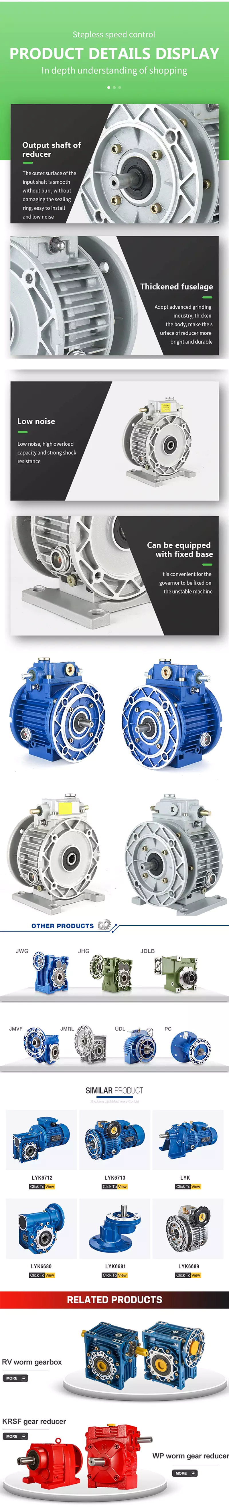
What Is a Speed Variator?
The speed variator is an electronic device that controls motor speed by varying the voltage applied to it. It consists of all the elements of a conventional variator (see Figure 1), as well as a protective circuit CP. This circuit protects the motor from overloads. The protection circuit requires a voltage -ve that represents the motor’s current during negative half-cycles.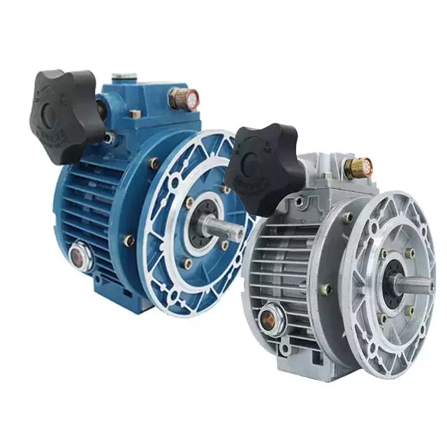
Mechanical continuous gear variator
A mechanical continuous gear variator (CVT) has many uses in cars and other vehicles. Its speed can be varied by altering the ratio of the primary and secondary pulleys. It is also used in conveyors, metal-cutting machines, and snowmobiles. Its main components include:
The mechanical continuous gear variator 100 comprises a driving shaft 1 and a gear 2. The driving shaft is coupled to a rotatably mounted transfer element 7. The variator includes an intermediate shaft 9, an output shaft 12, and a rotatably mounted frame 13.
The variator has two cone pulleys that are arranged in parallel. A V-belt runs between the two pulleys. The cones can be moved away or toward each other. When they approach each other, the belt runs around the center of each pulley. This makes it possible to vary the gear ratio within a wide range.
Variators have a wide variety of uses. They can be used in cars to make shifting more convenient. Variators can have up to six or eight gears, and they can also be used in manual sequential mode. Although they offer many advantages, they have a few disadvantages as well. One of the main disadvantages is their relatively small engine power. Consequently, most powerful cars are equipped with a mechanical gearbox.
Another disadvantage is the number of multiplier groups. There are two types of multiplier groups: first and second. In the case of a continuous gear variator, a multiplier group is present on the input shaft. Another multiplier group is connected to the output shaft through a transfer element. In this way, a mechanical continuous gear variator has three parts. In addition to the multiplier groups, the transmission can be controlled using different mechanisms.
Unlike its hydraulic counterpart, a mechanical continuous gear variator can change the output speed and torque. This variable speed transmission method can help maintain engine efficiency and minimize fuel consumption.
Intensity limiter
An intensity limiter for a Speed Variator is a device which protects a motor from overloads. This device employs a large portion of the variator’s elements to operate at very low currents and powers. As a result, it costs very little in addition to the variator.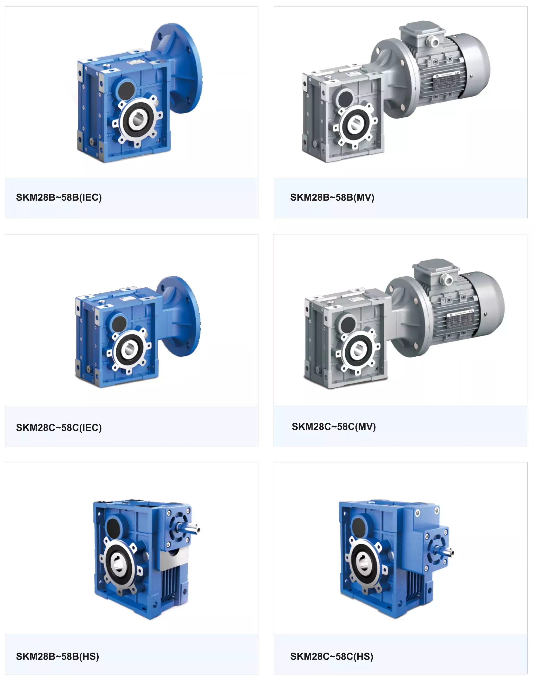
Hydrostatic transmission principle
Hydrostatic transmissions work on a simple principle: the prime mover pumps fluid to a hydraulic motor connected to a load. The motor’s speed is regulated by a variable displacement pump. The speed of the motor changes with the flow of the fluid, which causes the torque to vary. At high speeds, the power and torque remain constant, while lower speeds reduce power and torque.
The Hydrostatic Speed Variator utilizes the hydrostatic transmission principle and comprises two pump systems, one for a fixed displacement hydraulic motor and one for a variable displacement pump. The two pumps are self-contained within a single case, making them easy to maintain and service. In addition to a variable displacement pump, a Speed Variator’s secondary pump can be equipped with a dry friction and sealed enclosures.
Hydrostatic transmissions are designed to match the engine and load to optimize efficiency. While the hydrostatic transmission principle is similar to that of internal combustion engines, it is more efficient and can be customized for specific operating conditions. The important challenge in designing a hydrostatic transmission is balancing efficiency and performance. High efficiency machines tend to be slow in response while high-performance machines respond quickly.
A hydrostatic transmission can be a great alternative to conventional gear-based transmissions because it can allow for more precise vehicle movement. It can also be cheaper to install on machinery that already uses hydraulic power transmission. However, it is important to remember that a hydrostatic transmission requires the use of cooling systems to maintain high torque for extended periods of time.
The hydrostatic transmission principle of a Speed Variator uses a hydraulic circuit to control the output shaft. The hydraulic circuit controls the output speed and can be regulated. This allows for smooth operation, and reduces the shock load on the system. The hydrostatic transmission principle of Speed Variator works the same way as a hydraulic clutch.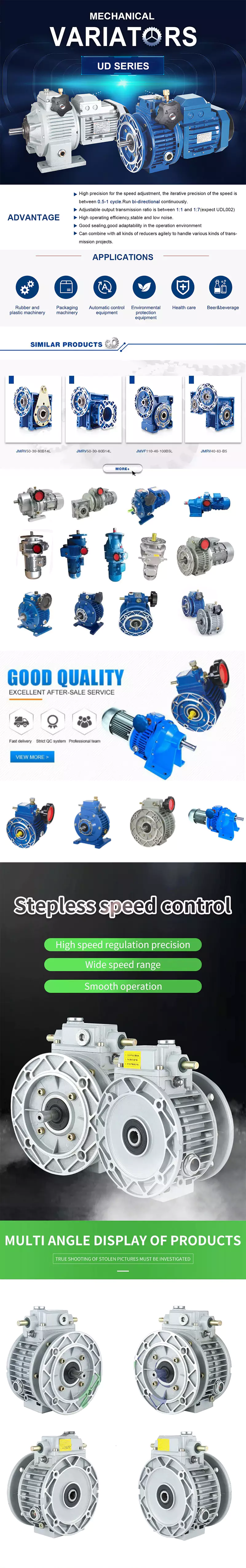
editor by czh